This article is contributed by a netizen.
Author: Chen Xianda
Original title: [Getting Started with Microcontrollers] (3) Learning the Path of Single-Chip Microcomputers from Application-Level Software Development ----- UART Serial Communication and C# Interaction
Original link: https://www.cnblogs.com/1996-Chinese-Chen/p/16826558.html
Introduction
In the first chapter blog, we discussed configuring the environment for Esp32 using Arduino, and learned about common bus communication protocols, including SPI, IIC, UART, etc. Today, I will bring you a case study of UART serial communication and C# serial port interaction, as well as what interrupts are, their role and practice. Without further ado, let's get started.
UART
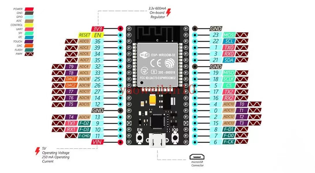
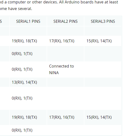
In the first blog, we mentioned that UART requires one receiving and one transmitting pin, a total of two, namely TXD (transmit pin) and RXD (receive pin). Regardless of the type of microcontroller, the serial port pins are these two; some may be missing the final D, but they are essentially the same. On the ESP32 development board, there are three pairs of UART pins, meaning the board has three serial ports available for use. As shown in the figure below, Serial0 corresponds to pins 1 and 3, Serial1 corresponds to pins 9 and 10, and Serial2 corresponds to pins 16 and 17. However, when we program the board, pins 1 and 3 cannot be used because when we connect the microcontroller to the computer via USB, the serial port pins used are 1 and 3. Therefore, we only have two available serial ports. On the Arduino IDE, the corresponding Serial also has four static classes: Serial, Serial1, Serial2, and Serial3. Although the number matches the three serial ports on the ESP32, only the first one can be used; the other two cannot be used because the corresponding pins do not match the ESP32 pins. As can be seen from the second figure below, the PINS of Serial1 and Serial2 do not align with the ESP32 pins, so we do not use them in serial port development; only the first Serial can be used.
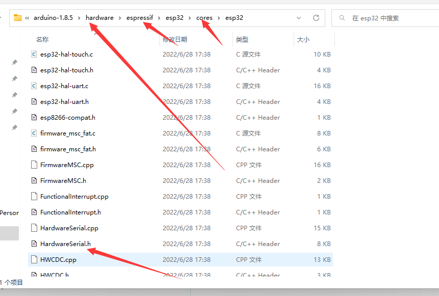
If we need to use the serial ports on the ESP32 for development, the ESP development package provides an official serial port library called HardwareSerial, which allows us to use the serial ports on the development board and specify the pins to the ones on our pin diagram. This library is located in the hardware/espressif/esp32/cores/esp32 directory under the Arduino IDE path. This folder contains some official ESP32 libraries. By using the HardwareSerial.h file, we can develop using the serial ports on the ESP32 development board. Next, let's understand how to use it in code.
Coding
In the code below, we have started a simple serial communication. In the first line of code, like in C language, we include the required library file. In the second line, we define a MySerial1 object of the HardwareSerial class. The constructor's value is 1, indicating that we will use the first serial port. In the setup function below, we start the MySerial1 serial object with a baud rate of 9600, data length of 8, parity NONE, stop bits 1, and the RX pin is 16, TX pin is 17. In the next line of code, we pass in a method called receiveEvent defined below. This method is used as a callback to receive serial data; we pass the pointer to this method. When the serial port receives data, it will enter this method.
The last line of code enables serial port 0 with a baud rate of 9600.
Some friends might be confused: in the pin diagram, pins 16 and 17 correspond to serial port 2, so why is it defined as 1 here? Actually, we can modify the definition of the serial port and its pins ourselves. The parameter passed to the constructor ranges from 0, 1, 2, corresponding to the three UART serial ports on the development board. The pins passed in the begin method have no relation to the 0,1,2 values, but the passed pins must be one of the three UART serial ports on the development board. So we could also define MySerial2.begin(9600, SERIAL_8N1, 10, 9); The 0,1,2 only correspond to the three pairs of serial ports; they do not specify the pins. In the begin method, we specify the pins for the corresponding serial port.
In the callback for receiving serial messages below, the first line of code calls the available method, which returns an int parameter. We could also write available() > 0 here, which is fine. This method reads the length of the data we have received from the serial buffer. If this condition is true, it means we have received data. Then inside, we start reading the data.
All Serial classes inherit from the Arduino Stream base class, which provides some methods for data processing. In the code below, we convert the read data to a string, then delay for one second. After that, we use our serial port object to write the received data to the buffer. The buffer will then send out the data we wrote, i.e., the parameter passed to println will be sent to the sender of the serial data. Whoever sent the data will receive "i am receive!!" + str.
#include <HardwareSerial.h>
HardwareSerial MySerial1(1);
void setup() {
  // put your setup code here, to run once:
  MySerial1.begin(9600, SERIAL_8N1, 16, 17);
  MySerial1.onReceive(receiveEvent);
  Serial.begin(9600);
}

void loop() {

}
void receiveEvent()
{
  if(MySerial1.available())
  {
     String str = MySerial1.readString();
     delay(1000);
     MySerial1.println("i am receive!!" + str);
  }
  delay(1000);
}
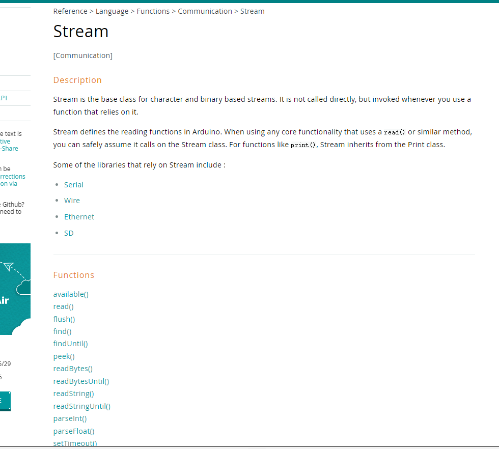
The Stream class includes the following methods. Classes that inherit from Stream include the serial port, the Wire (I2C communication), the SD card class, and the Ethernet class for network connections. All of these can use these methods to operate on data.
C# Coding
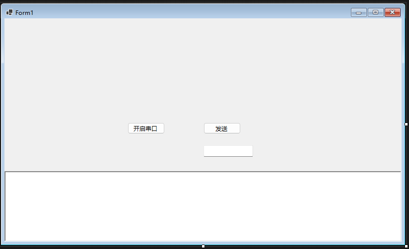
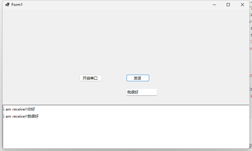
The C# code is much simpler. The interface includes a button to open the serial port, a button to send data along with a text box, and a text box to display received data.
In the code, we open the serial port, specifying which port to open. Some properties need to be set the same as on the ESP32 side. Above, we set the baud rate to 9600, data bits to 8, stop bits to 1, and parity to NONE. So in C#, we also need to set these accordingly. However, the parity is NONE by default, so we don't set it here. Then we open the serial port and register a callback for receiving data. We define a byte array of 1024, read data from the serial port, and return the length of the data read. Then we truncate the byte array to the actual length, convert it to a string using UTF-8 encoding, and display it in the rich text box on the interface. In the send button event, we read data from the input box, convert it to a byte array, and write the data to the serial port.
public partial class Form1 : Form
    {
        private SerialPort serialPort = new SerialPort("COM6");
        public Form1()
        {
            InitializeComponent();
        }

        private async void button1_Click(object sender, EventArgs e)
        {
            serialPort.BaudRate = 9600;
            serialPort.StopBits = StopBits.One;
            serialPort.DataBits = 8;
            serialPort.Open();
            serialPort.DataReceived += (a, b) => {
                var serial = a as SerialPort;
                var data = new byte[1024];
                var res = serial.Read(data, 0, data.Length);
                data = data[..res];
                string st = Encoding.UTF8
                .GetString(data);
                BeginInvoke(() => { richTextBox1.Text += st; });
            };
        }

        private void button2_Click(object sender, EventArgs e)
        {
            var str = Encoding.UTF8.GetBytes(textBox1.Text);
            serialPort.Write(str, 0, str.Length);
        }
    }
Wiring Diagram
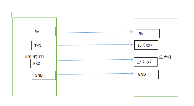
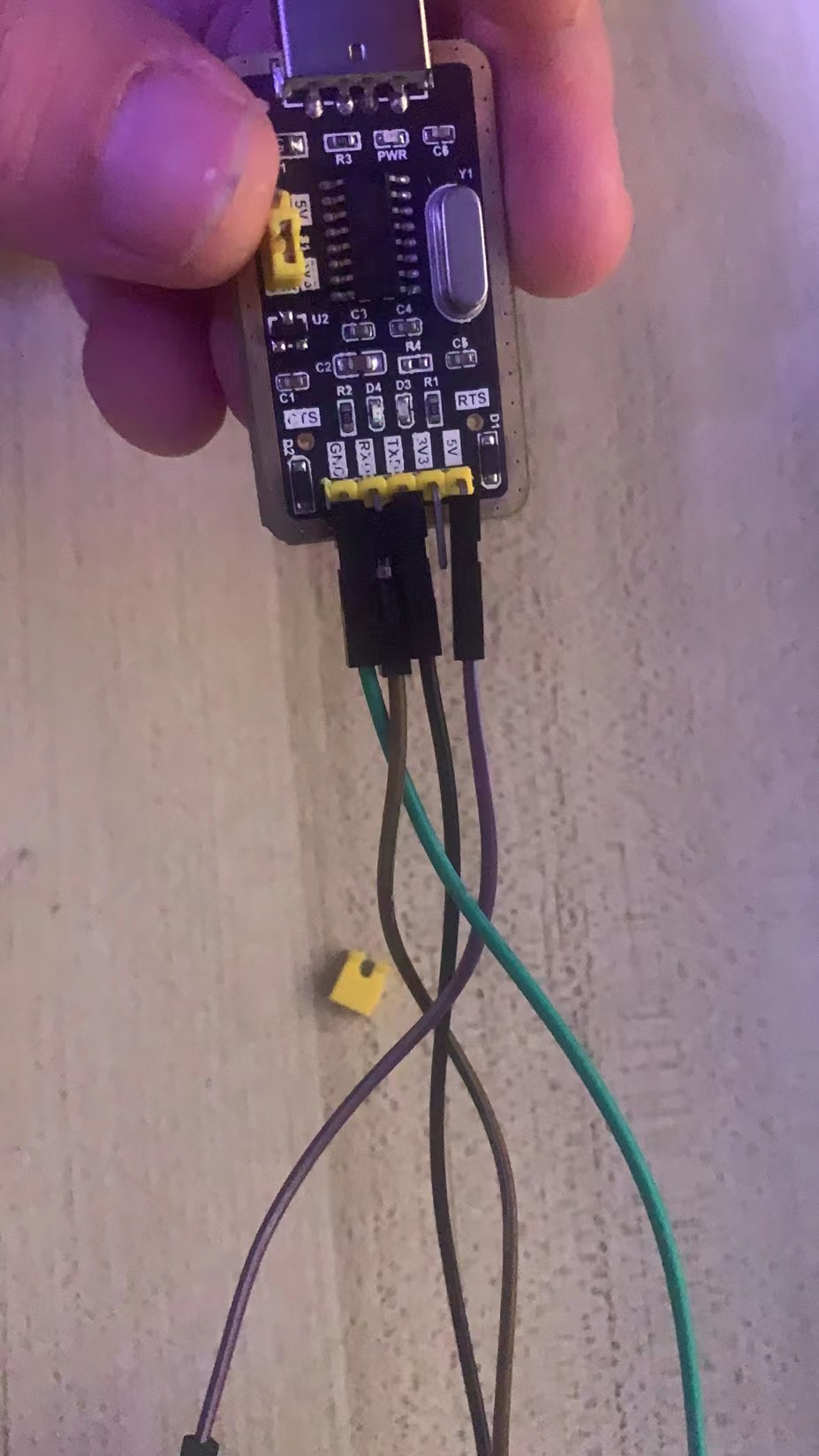
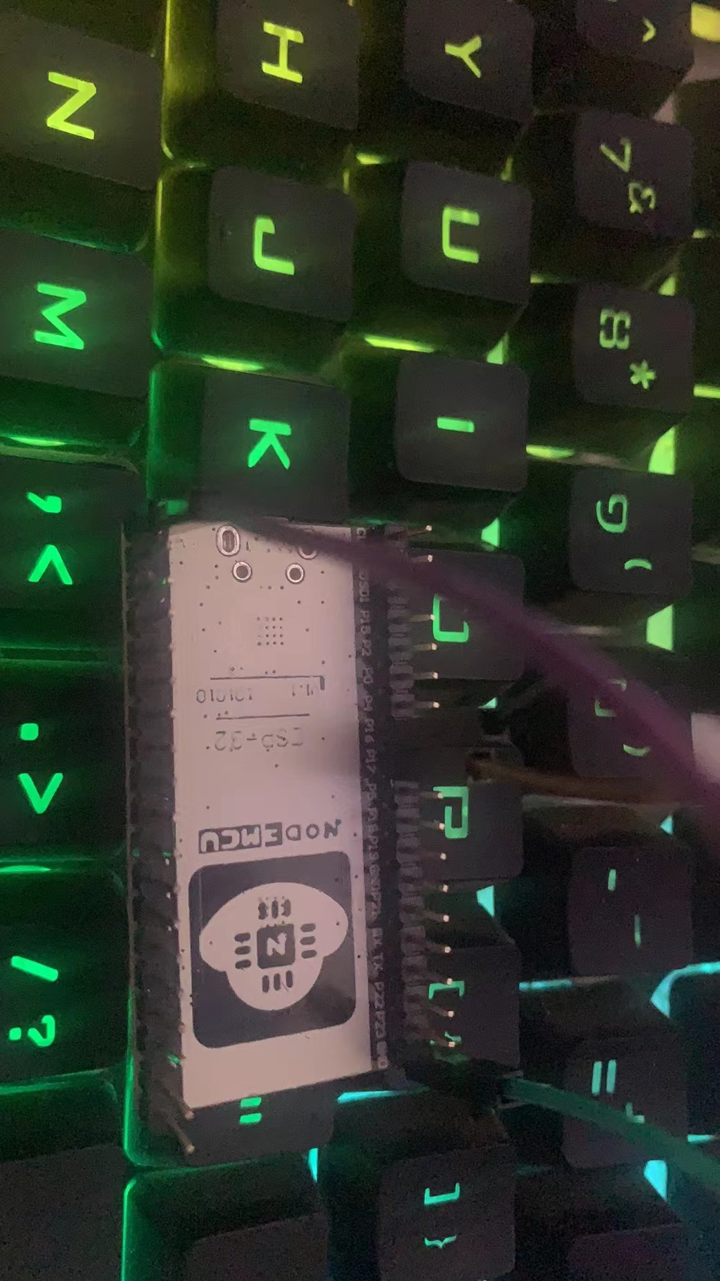
For this example, we need to prepare a USB to TTL module and four female-to-female DuPont wires. After programming the board, we need to use the DuPont wires to connect the USB to TTL module to the microcontroller. Connect VCC or 5V to the 5V pin of the microcontroller. Connect the GND of the USB to TTL module to the GND of the microcontroller. Then connect the RXD pin of the USB to TTL module to pin 17 of the microcontroller, and the TXD pin to pin 16 of the microcontroller, as shown in the wiring diagram below. Do not reverse the 5V and GND connections, as this may damage the module. After confirming the wiring is correct, insert the USB to TTL module into the computer. Then run the C# program in the code, click to open the serial port, send data, and you should receive feedback from the microcontroller.
Conclusion
Serial communication is an indispensable communication method in IoT. Typically, RX is connected to TX and TX to RX, unless otherwise specified by the module manufacturer. This is the standard wiring. In future lessons, I will sequentially explain IIC, PWM, SPI, and interrupts in detail. Welcome everyone to follow, learn, and discuss. I will share everything I know. Meanwhile, there will also be tutorials on the STM32 series. If you are interested, you can join the QQ group 822084696 to discuss together.