本文由网友投稿。
作者:陈显达
原文标题:【单片机入门】(三)应用层软件开发的单片机学习之路-----UART 串口通讯和 c#交互
原文链接:https://www.cnblogs.com/1996-Chinese-Chen/p/16826558.html
引言
在第一章博客中,我们讲了 Arduino 对 Esp32 的一个环境配置,以及了解到了常用的一个总线通讯协议,其中有 SPI,IIC,UART 等,今天我为大家带来 UART 串口通讯和 c#串口进行通讯的一个案例,以及什么是中断,中断的作用和实践,话不多说,让我们正式开始。
UART
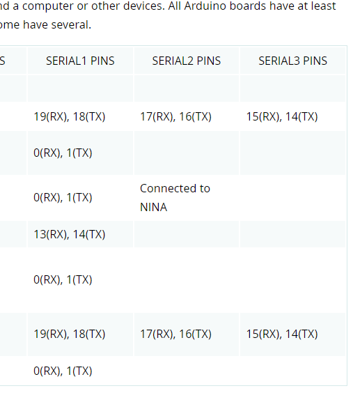
在第一篇博客中,我们讲了 UART 是需要一个接收一个发送的引脚,总共两个,分别是 TXD(发送引脚),RXD(接收引脚),不管是什么类型的单片机串口引脚都是这两个,可能有的是少了最后面的那个 D,但是都是一样的东西,在 ESP32 的开发板上,是有三对 UART 的引脚的,也就是说板子上有三个串口可以供我们使用,如下图,Serial0 对应的引脚为 1 和 3,Serial1 对应的引脚为 9 和 10,Serial2 对应的引脚为 16 和 17,但是在我们烧录的时候,1 和 3 是不能使用的,因为我们通过 USB 将单片机连接到电脑上,使用的串口引脚就是 1 和 3,所以我们可使用串口只有两个,而 Arduino IDE 上面,对应的 Serial 也有四个静态类,分别是 Serial,Serial1 和 Serial2 以及 Serial3。虽然他的数量和我们 ESP32 的串口数量是一样,但是只有第一个可以使用,后面两个我们是无法使用的,因为后面两个对应的引脚和我们 ESP32 的引脚是不相同的,我们可以从下面第二个图看到,Serial1,Serial2 的 PINS 是和我们 ESP32 的引脚是对不上的,所以我们在串口开发的时候是不使用这两个,对于第一个 Serial 我们是可以使用的。
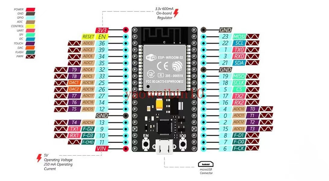
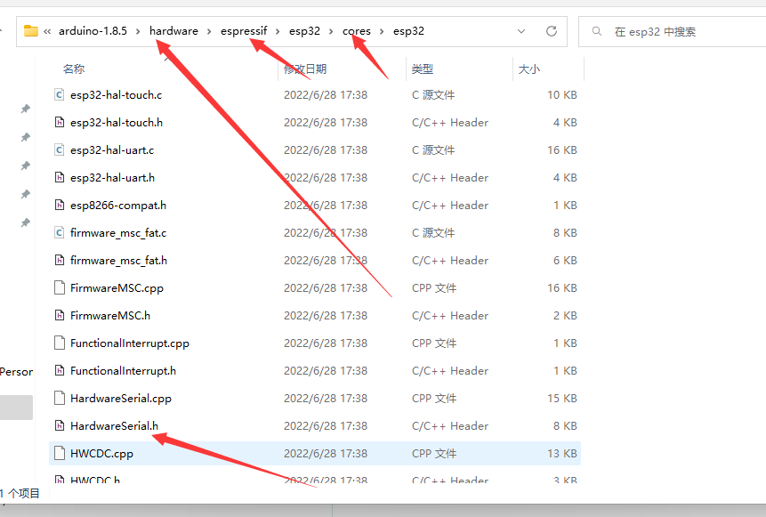
我们如果需要使用 ESP32 的串口开发,在 ESP 的开发包里,官方给我们提供了一个 HardwareSerial 的一个串口库,里面我们可以使用开发板上面的串口,同时将引脚指定为我们引脚图上面的引脚。这个库的位置为我们 Arduino IDE 目录下的 hardware/espressif/esp32/cores/esp32 可以找到这个库,这个文件夹下包含了一些 ESP32 的官方库;使用这个 HardwareSerial.h 文件我们可以实现使用 ESP32 开发板上面的串口进行开发,接下来我们在代码中去了解他如何使用。
编码
在下面的代码中,我们开始了一个简单的一个串口通讯,在代码第一行,是和 c 语言一样引入我们需要的库文件,然后在第二行,定义了 HardwareSerial 这个类的一个 MySerial1 对象,里面的构造函数的值是 1 代表着,我们将使用第一个串口,在下面的 setup 里面,我们开始启动了 MySerial1 这个串口对象,启动的波特率是 9600,数据长度是 8,校验位是 NONE,停止位是 1,以及串口的 rx 的引脚是 16,tx 的引脚为 17。在下一行代码,我们传入了一个我们下方定义的 receiveEvent 的一个方法,这个方法用来接收串口接收数据的一个回调,将我们这个方法指针传入进去,在串口接收到数据之后,会进入到我们这个方法中。
最后一行代码,我们是启用了第 0 个串口,波特率是 9600。
可能上面的代码有朋友就有疑惑了,明明 16 和 17 在引脚图中定义的串口是 2,为什么这里定义的是 1 呢,实际上这个我们可以自己修改这个串口的定义和引脚,这个构造函数传入的参数取值范围为 0,1,2,对应的是我们开发板上的三个 UART 串口,在 begin 哪里传入的引脚和这个 0,1,2 是没有任何关系的,但是这个传入的引脚必须是开发板上三个 UART 串口之一,所以我们也可以定义为 MySerial2.begin(9600,SERIAL_8N1,10,9);这里的 0,1,2 仅对应有三对串口,不指定对应的引脚,在 begin 方法我们指定对应的串口的引脚。
在下面的接收到串口消息的回调中,我们第一行代码调用了 available 这个方法,这个方法返回的是一个 int 参数,当然了我们这块也可以写 available()>0,也是可以的,这个方法是从串口缓存中读取我们接收到的数据长度,这个条件成立,说明我们是有接收到数据,然后在里面我们开始去读取数据。
在所有的 Serial 都是及程序 Arduino 的一个 Stream 的一个基础类,这个类提供了一些我们对数据处理的一个方法,所以在下面的代码中,我们将读取的数据转为字符串,然后将代码延迟暂停了一秒,随后,我们使用我们的串口对象,将接收到的数据写入缓冲区,缓冲区会把我们写入的数据,在发送出去,即将 println 里面传入的参数发送到我们的串口发送方,谁发的数据,谁就会收到"i am receive!!"+str。
#include <HardwareSerial.h>
HardwareSerial MySerial1(1);
void setup() {
  // put your setup code here, to run once:
  MySerial1.begin(9600,SERIAL_8N1,16,17);
  MySerial1.onReceive(receiveEvent);
  Serial.begin(9600);
}

void loop() {

}
void receiveEvent()
{
  if(MySerial1.available())
  {
     String str= MySerial1.readString();
     delay(1000);
     MySerial1.println("i am receive!!"+str);
  }
  delay(1000);
}
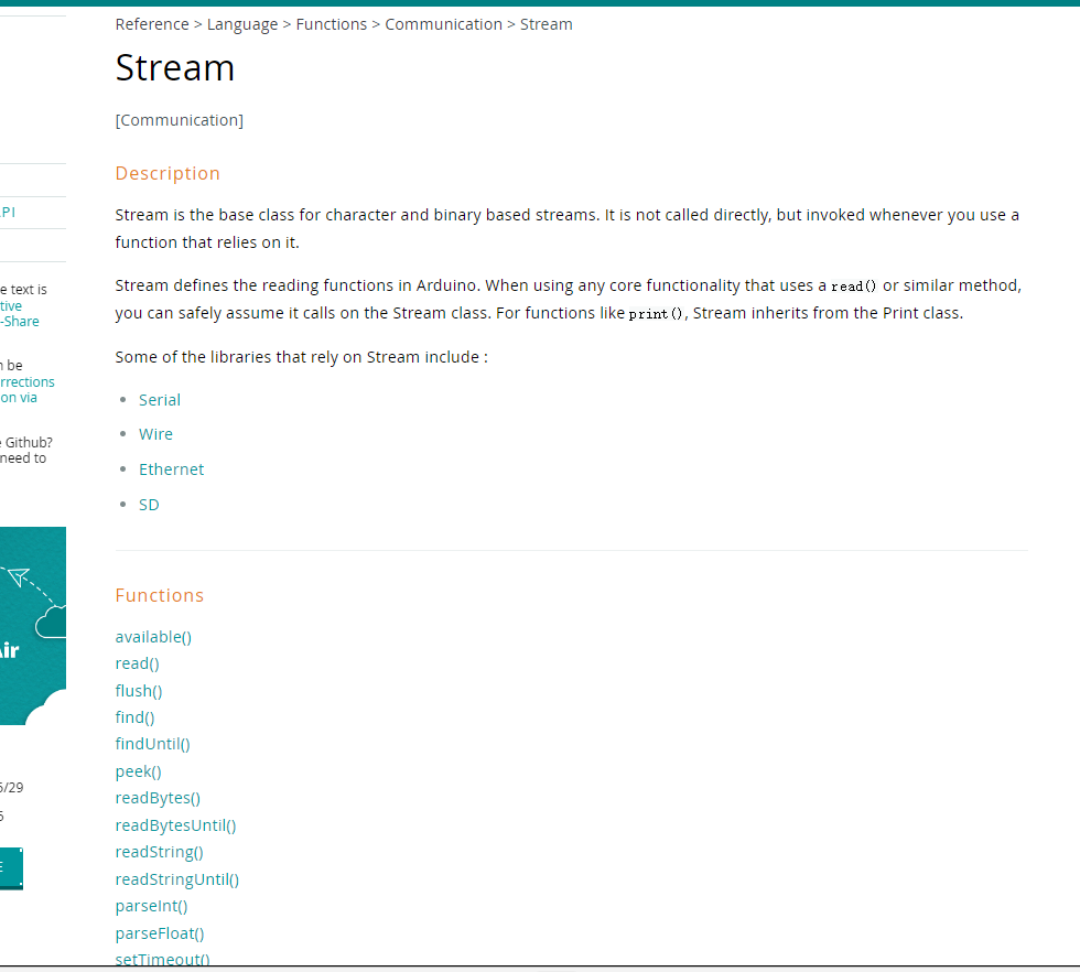
Stream 包括了以下方法,其中继承 Stream 的分别为串口,IIC 通讯的 Wire,SD 卡的一个类,以及用于网络连接的 Ethernet 类,都可以使用这些方法用来对数据进行操作。
c#编码
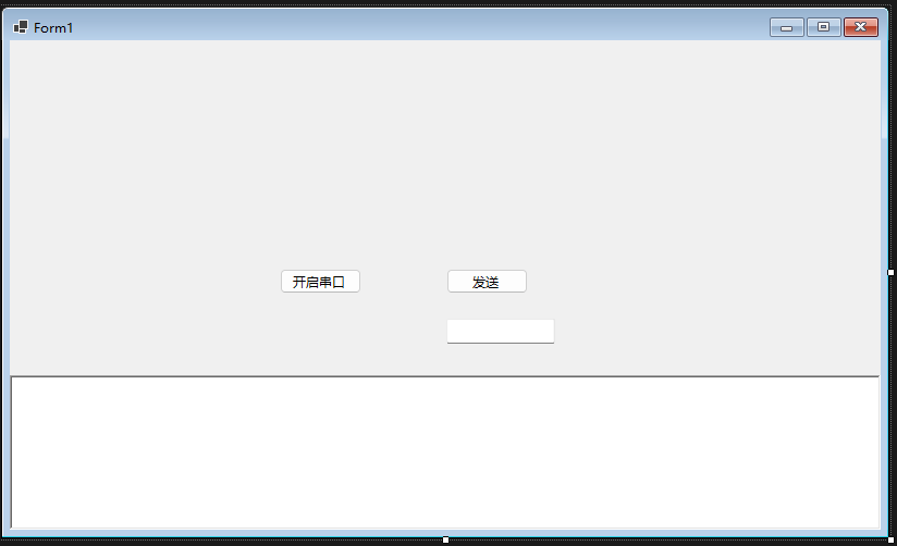
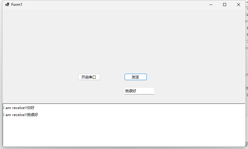
C#方面的代码则简单很多,界面一个开启串口的按钮,一个发送数据的按钮和文本框,以及用来接收数据显示的文本框。
在代码中我们开启了串口,指定了打开的是哪一个串口,一些属性是需要和 ESP32 那边设置一样的,在上面我们设置波特率为 9600,数据为是 8,停止位是 1,校验位是 NONE,所以在 c#这边我们也需要这样设置,不过校验位默认是 NONE 的,所以此处我们没有设置,然后开启串口,注册了一个接收到数据的一个回调,然后定义一个 1024 的字节数组,从串口读取数据,返回读取的数据长度,然后在对刚才定义的 1024 字节数组进行截取,然后通过 UTF-8 的格式转为字符串,然后显示到界面上的富文本框中,在发送按钮事件中,我们从输入框读取数据转为字节数组,然后将数据写入到串口中去即可。
public partial class Form1 : Form
    {
        private SerialPort serialPort = new SerialPort("COM6");
        public Form1()
        {
            InitializeComponent();
        }

        private async void button1_Click(object sender, EventArgs e)
        {
            serialPort.BaudRate = 9600;
            serialPort.StopBits = StopBits.One;
            serialPort.DataBits = 8;
            serialPort.Open();
            serialPort.DataReceived += (a, b) => {
                var serial = a as SerialPort;
                var data = new byte[1024];
                var res=serial.Read(data,0, data.Length);
                data = data[..res];
                string st = Encoding.UTF8
                .GetString(data);
                BeginInvoke(() => { richTextBox1.Text += st; });
            };
        }

        private void button2_Click(object sender, EventArgs e)
        {
            var str = Encoding.UTF8.GetBytes(textBox1.Text);
            serialPort.Write(str, 0, str.Length);
        }
    }
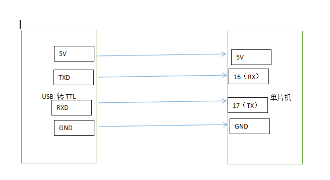
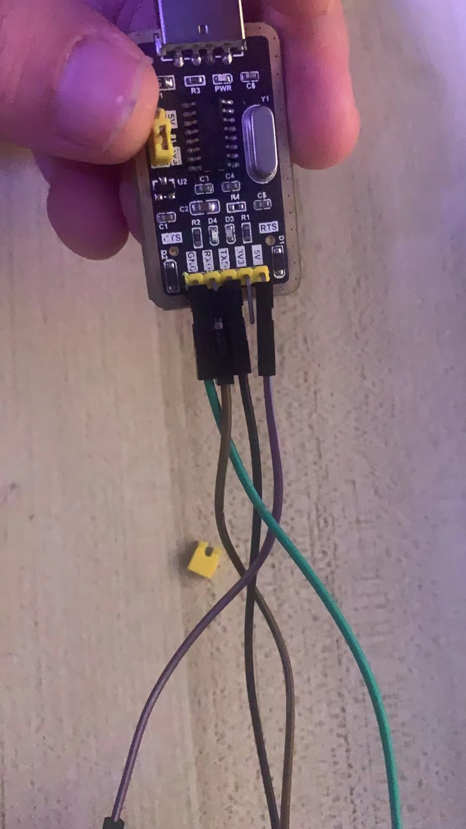
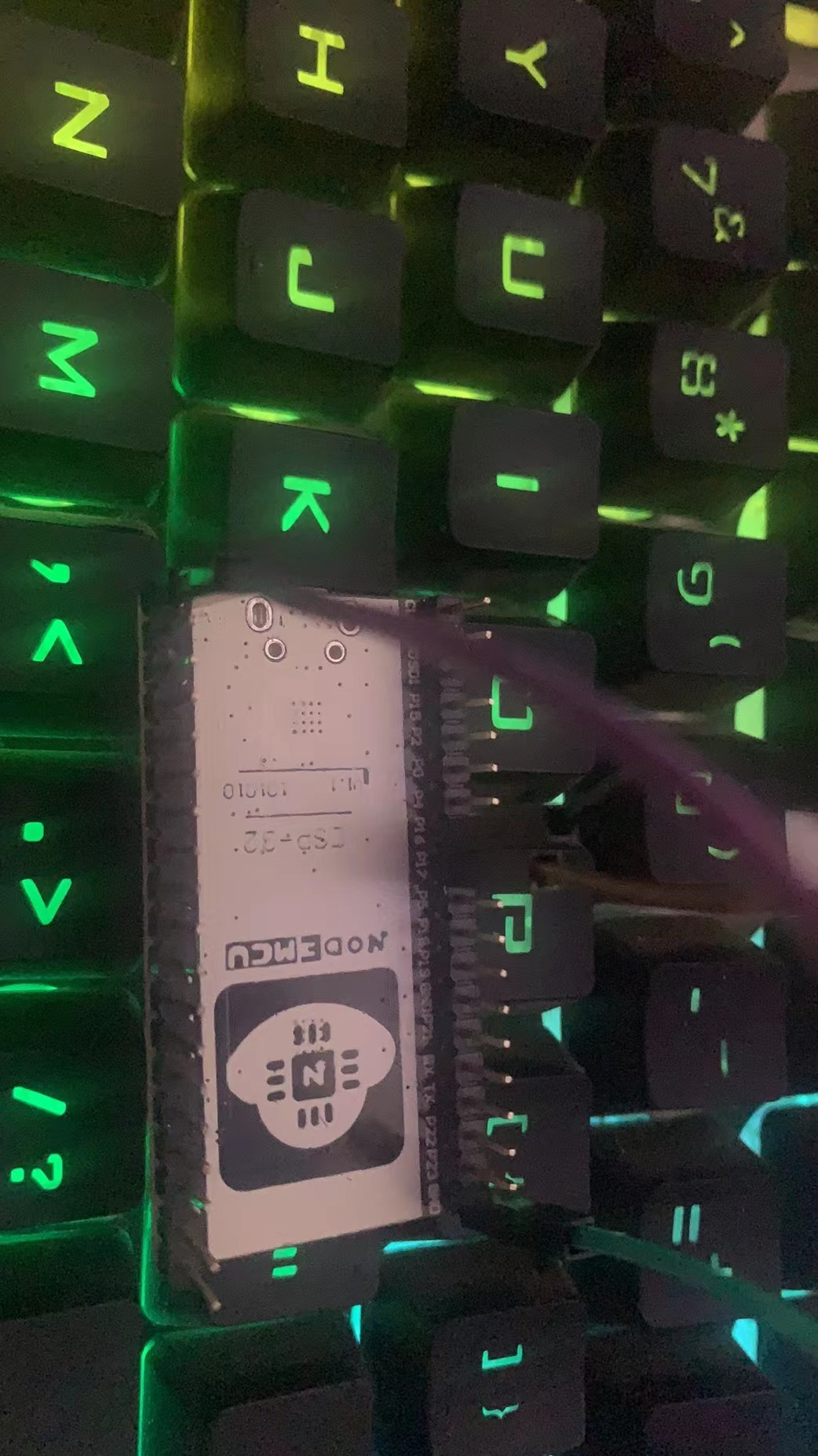
接线图
在此处的实例,我们需要准备一个 USB 转 TTL 的模块,四根母对母的杜邦线,在程序烧录之后,我们需要将使用杜邦线让 USB 转 TTL 模块和单片机进行连接,VCC 或者 5V 接单片机的 5V 引脚,USB 转 TTL 的 GND 和单片机的 GND 相接,然后 USB 转 TTL 的 rxd 引脚和单片机 17 引脚相接,txd 引脚和单片机的 16 引脚相接,如下图所示接线,5v 不可和 gnd 接反,否则可能会烧坏模块,确认接线无误后,将 USB 转 TTL 模块插入电脑中,然后代码中运行 c#程序,电机开启串口,随后发送数据,可以接收到单片机的反馈。
结语
串口通讯是物联网中,必不可少的一种通讯方式,通常情况下都是 RX 接 TX,TX 接 RX,除非是模块厂商的规定,否则都是这样接线,在后面的课程中,我会依次对 IIC,以及 PWM,还有 SPI,以及中断单独做一个讲解,欢迎大家关注,学习和探讨,我会将我所知道的都会分享,同时,后面也会有 STM32 系列的教程。如果有感兴趣的朋友,可以加 QQ 群一起来讨论 822084696。