本文由网友投稿。
作者:陈显达
原文标题:【单片机入门】(四)应用层软件开发的单片机学习之路-----ESP32 开发板 PWM 控制电机以及中断的使用
原文链接:https://www.cnblogs.com/1996-Chinese-Chen/p/16846218.html
引言
各位大佬,晚上好啊,在上一篇博客中,我们讲了什么是 UART 串口通讯,以及使用 USB 转 TTL 使得单片机可以和 c#上位机做一个串口通讯,接下来,为大家带来 PWM 的概念原理,以及实际案例,使用 PWM 对电机进行速度调制,因为本课程的最后是做一个红外遥控的智能小车,所以是需要电机四个,驱动四个,轮胎四个,所以 PWM 对于最后的成果也是极为重要,并且在实际开发中,PWM 也是比较常用的调速方式。
概念
PWM 全称 Pulse width modulation,中文翻译为脉冲宽度调制,其基本原理为控制方式就是对逆变电路开关器件的通断进行控制,使输出端得到一系列幅值相等但宽度不一致的脉冲,用这些脉冲来代替正弦波或所需要的波形。也就是在输出波形的半个周期中产生多个脉冲,使各脉冲的等值电压为正弦波形,所获得的输出平滑且低次谐波少。按一定的规则对各脉冲的宽度进行调制,既可改变逆变电路输出电压的大小,也可改变输出频率。
可能上面对于原理的解释过于官方,大家可能看不懂,通俗易懂的来说,就是通过对电子元器件的电路进行高低电平进行控制,在一段时间内,高低电平在输出会形成一段波动,这个波动可以成为 PWM 波形,而我们需要使用代码去控制 PWM 的输出波形,高电平在这一段波动中,通电时间即高电平时间是占了总时间多少,同时在这一段 PWM 波形中,高低电平来回切换的频率又是多少,形成了这么一段波形,这就引入了两个概念,占空比(Duty Ratio)和频率,占空比代表着,高电平通电总时和总时的一个占比(这段波形中,高低电平的总共占用时间),而频率则是高低电平在这段波形中,来回切换的一个频率。
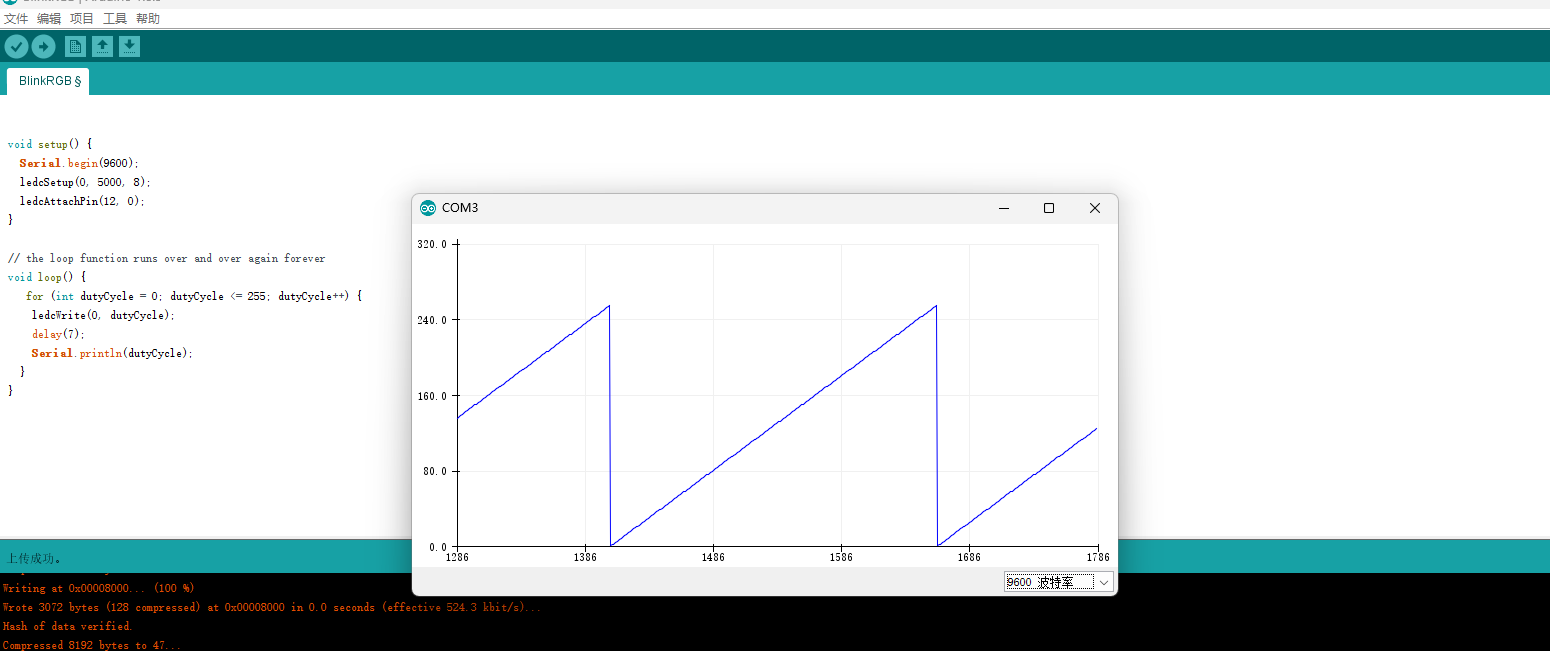
如下图,下方在 Arduino 串口绘图器中,展示了一段锯齿波形,看下方的 GIF 我们可以看到对应的电机运动也是有快到慢的一个运动状态。
代码解析
void setup() {
  Serial.begin(9600);
  ledcSetup(0, 5000, 8);
  ledcAttachPin(12, 0);
}

// the loop function runs over and over again forever
void loop() {
   for (int dutyCycle = 0; dutyCycle <= 255; dutyCycle++) {
    ledcWrite(0, dutyCycle);
    delay(7);
    Serial.println(dutyCycle);
  }
}
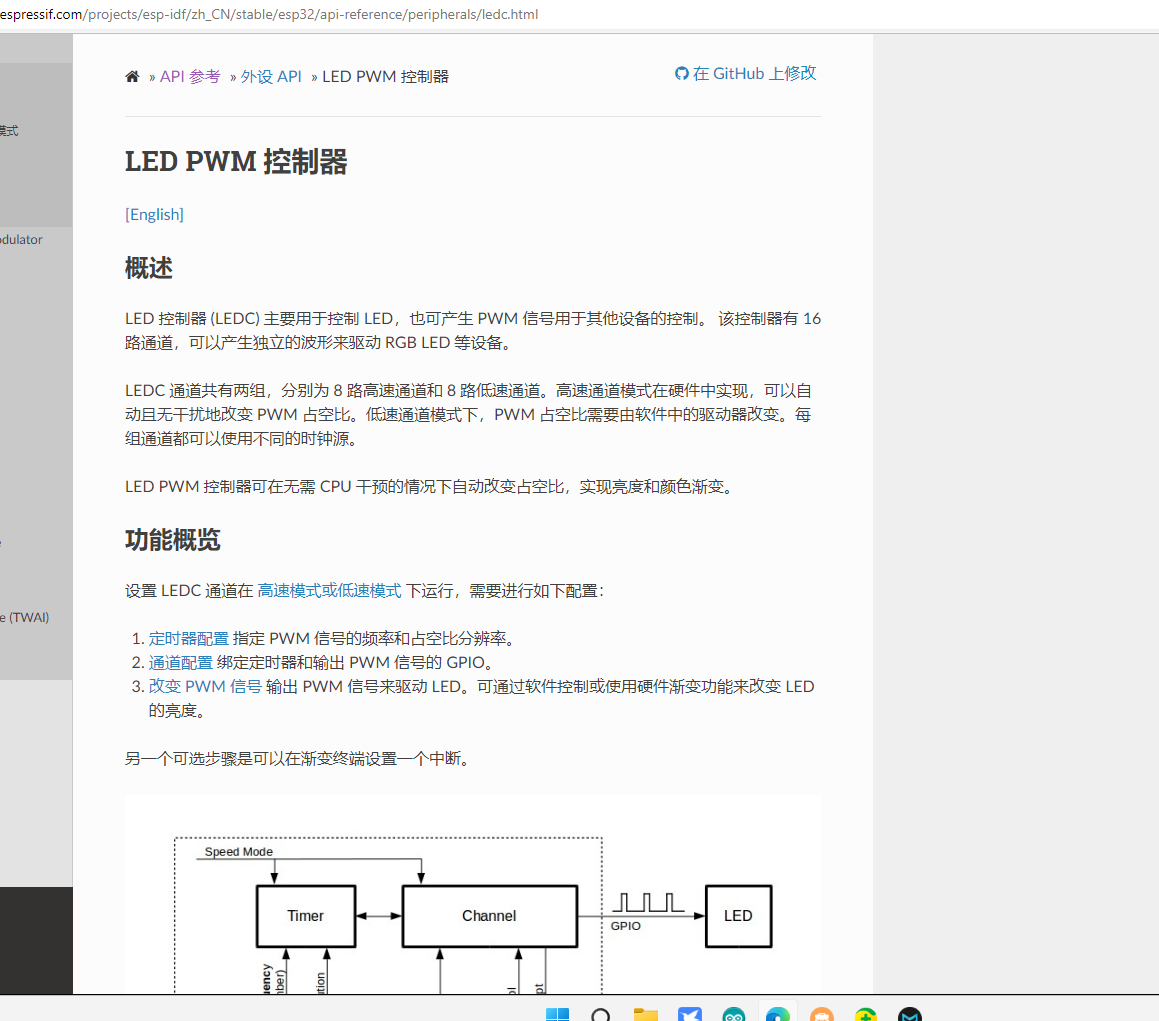
在 Arduino 中我们可以使用 LEDC 来实现对 PWM 的控制,而在纯 c 乐鑫的开发板中,是可以使用 MCPWM 进行控制,但是由于 Arduino 在此处不能使用 MCPWM,则就有了 LEDC 作为替代品,ESP32 带有一个 16 通道的一个 LED PWM 控制器,对应使用的是乐鑫的 LED PWM 控制,ESP32 LED PWM,分为 8 路高速通道和 8 路低速通道,然后我们使用不同的频率,和占空比来实现控制电机转速的控制。
在上面的代码中,我们先设置了 ledc 的通道为 0,频率为 5000,第八个低速 LED 控制器,即代码为 ledcSetup(0, 5000, 8);然后需要将通道和引脚进行管理使用 ledcAttachPin(12, 0);将引脚 12 和第 0 个通道关联起来,在 loop 代码中,可以看到,我们写入的最大的占空比为 255,而 0-255 总数为 256,那是因为,占空比是和通道是有关系的,上文提到,LED 的 PWM 控制器一共有 16 个,此处我们使用 8,而 256 则为 2 的 8 次方的值,所以占空比最大为 256,如果取值为 10,占空比的最大值则为 1024-1;ledcwrite(0,dutyCycle);则是将占空比写入对应的通道,便完成了 PWM 对电机进行调速设置。
Arduino 针对 ESP32 乐鑫 PWM 的封装,目前已知的有 LEDC,不需要安装,默认就可以使用,而其他的也有对于 PWM 的封装,个人测试了一两个倒也没有这个好用,后续各位朋友也可以继续探索其他好用的 PWM 库进行开发。
中断
在上面讲完 PWM 之后,我们再来讲一下中断,以及中断的一个实际案例。中断,顾名思义,是在程序执行期间,遇到某一个事件的时候,将暂停手上的工作先去执行某一件事情,这个事情则是我们中断当下工作,去执行的事情,这个动作,称之为中断。虽然在代码中,可以注册一个后台任务(在纯 c 中),进行不停的 while,但是这样在性能上还是无法发挥单片机的功效,所以这种场景下我们便需要使用中断,来实现我们的某种功能,例如使用按钮,来判断是否需要打开 LED,或者是其他的行为。
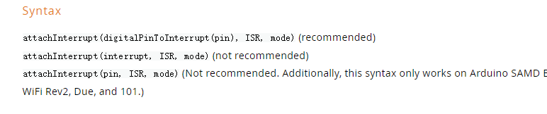
在 Arduino 中,我们可以使用 attachInterrupt 函数来进行对引脚增加中断以及使用 detachInterrupt 来移除中断,
attachInterrupt 函数需要三个参数,第一个为中断需要使用的引脚 pin,第二个为中断触发的函数,第三个为中断的类型,对于 ESP32 的中断,在 Arduino 中,其方法名前面必须加一个 IRAM_ATTR 标记其为中断函数,第一个函数中的 digitalPinToInterrupt 为将 27 和中断进行一个绑定,同时还有其他方法,但是官方均不推荐,
在下方的代码中,我们定义了一个 change 的函数用来处理 ESP32 27 引脚的中断,用 27 引脚的电平控制 LED 引脚 2 的电平,以此来控制是否点亮 LED 灯,先设置引脚 2 为输出模式,27 引脚为上拉输入模式,可以理解为上拉电阻的一般都需要用到这种模式,然后我们将引脚 27 和中断进行关联,设置中断函数为 change,模式为 CHANGE。然后在 LOOP 函数中,我们给引脚 2 写入 state 的值,当进入 change 中断函数中,会将 state 取反,然后进入 loop 写入值。以此实现控制 LED 的显示和不显示,在这里,提醒一下,由于在单片机中,中断以及定时器都是非阻塞模式,而 Serial.println 函数是阻塞写入缓冲区,会导致中断函数会不断的输出错误,错误:Guru Meditation Error: Core 1 panic'ed (Interrupt wdt timeout on CPU1).
这是因为 println 函数阻塞导致定时器无法继续执行,所过非要使用此函数,可以尝试设置中间变量,然后在 loop 函数中判断是否改变值,然后进行输出信息到串口。
可以在下方 GIF 看到,我们使用按钮进行控制 LED 的显示和不显示。
volatile byte state = LOW;

void IRAM_ATTR change()
{
   state=!state;
}
void setup() {
  // put your setup code here, to run once:
  Serial.begin(9600);
  pinMode(2, OUTPUT);
  pinMode(27, INPUT_PULLUP);
  attachInterrupt(digitalPinToInterrupt(27), change, CHANGE);
}

void loop() {
  digitalWrite(2, state);// put your main code here, to run repeatedly:
}
可以看到第二个方法是传入一个 interrupt 的中断编号,但是 ESP32 上面的中断编号,不在官方资料中,所以我们只有需要第一个方法来进行引脚和中断函数的关联,当然了可能最后一个也是可以,只是此处我没有尝试,感兴趣的可以进行尝试,
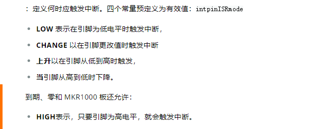
在 mode 中,Arduino 是支持五种模式,第一种为 LOW,,看翻译我们知道,这个是在电平处于低电平时会触发中断函数,
第二个 CHANGE 是不管是高到低,还是低到高,都会触发
第三种是引脚在由低电平到高电平时触发,而不是已经到了高电平触发,
第四种是下降,当电平由高到低时会触发中断函数,
第五种是电平处于高电平时会触发中断函数。
结语
今天讲了 PWM 还有中断的使用,可能一次性讲的有点多,有点难以消化,有什么不懂的可以及时问我,以及后面我更新的时间会稍微慢一点,防止讲的过快,一时间不明白,后面还会有对于 IIC,SPI 的一个案例讲解,在这些讲完后,我会开始准备最终极的目标,做一个智能小车,其中会需要的配件,这两天我会总结好发到群里,以及购买链接。有感兴趣的同学可以加 QQ 群,一起学习,一起讨论,博主也是一个刚开始玩单片机的学徒,后面也会研究 stm32 系列单片机,欢迎大家加入讨论,学习。