本文由网友投稿,站长是一点都不懂硬件。
作者:陈显达
原文标题:【单片机入门】(一)应用层软件开发的单片机学习之路-----基础知识入门
原文链接:https://www.cnblogs.com/1996-Chinese-Chen/p/16786374.html
引言
工作了五六年,一直都是以软件为主,期间也是各个方向都玩,移动端,PC 端,网页端,后面在去年西安疫情的那一个月,突然觉得硬件也有很多可玩之处,相比于软件,看得见摸得着的东西可能更容易令人接受,做出成品也更容易有成就感,所以在那段时间我就去研究了一下树莓派,然后当时用 node 还有 c#操控树莓派来进行和传感器等电子元器件进行交互,感兴趣的可以看看我之前的文章C#控制树莓派入门 - 四处观察 - 博客园 (cnblogs.com),这篇文章仅仅用了做树莓派的入门,实际上,和我们这篇单片机的入门实际上也是有一些共性相通的地方。接下来,让我们一起了解一下单片机的入门基础知识吧。
何为单片机
单片机。最小计算机运行系统,百度百科做的解释集成电路芯片,是采用超大规模集成电路技术把具有数据处理能力的 CPU、随机存储器 RAM、只读存储器 ROM、多种 I/O 口和中断系统、定时器/计数器等功能(可能还包括显示驱动电路、脉宽调制电路、模拟多路转换器、A/D 转换器等电路)集成到一块硅片上构成的一个小而完善的微型计算机系统,在工业控制领域广泛应用。从上世纪 80 年代,由当时的 4 位、8 位单片机,发展到现在的 300M 的高速单片机。
可以看到,一个单片机基本上可以当作是一个小型计算机,具有存储,计算,输入和输出,计时定时器等能力,当然了,我们一台完整的计算机与我们进行交互,也是通过 IO 去进行交互,通过鼠标或者键盘连接到 IO 口上就可以在计算机上面进行输入输出,那普通的单片机上面的输入输出就需要通过单片机上面的 IO 口,就是那些针脚去进行通讯,可以看如下图,这是一个 ESP32 的一个单片机,上面包括了那么多的 IO 引脚,统称为 GPIO,那么这个 GPIO 是何方神圣呢,GPIO 的全称是 General-purpose input/output,翻译过来也就是通用的输入输出接口,在这个单片机上面一共有四十个 gpio 接口。
单片机接口
按照 GPIO 分类可以分为:
POWER,电源接口,下图这个开发板上面有一个 3.3V 和一个 5V 的一个电源接口,同时可以用来做输入或者输出电源,用来给单片机进行供电,或者复杂的接串联给整体项目中的所有电子元器件进行供电。
GND:电线接地端接口,上面的 POWER 是正极,那么 GND 就是电路中的负极,或者接地线路。
GPIO:就是可以作为通用的输入输出接口,可以用来和电子元器件进行交互,例如让一个 LED 灯亮起来,可以使用 GPIO 的输出高低位来进行让 LED 亮起来,高低位,则是给电子元器件进行释放电流或者关闭电流就是一个开关,这里不做过多解释,后面我们会做实验一步一步,让大家学会。
ADC:模数转换器,将输入的一个模拟信号的电压,转为数字,将输入的模拟电压或电流转换为表示电压或电流的大小的数字,获取到采集的数据,然后转为具体的数字,例如温度传感器,气压传感器等等,都是通过获取的模拟信号电压,转为具体的数字。
CONTROL:控制引脚,通常单片机带了一个 EN 的按钮用来重启单片机,如果将线路接入到这个 EN 引脚则可以控制单片机进行重启。
UART:串口通讯的一种,通用异步收发传输器(Universal Asynchronous Receiver/Transmitter),同一套 UART,具有两个引脚,一个是 RX,一个是 TX 引脚,RX 用来接收数据,TX 引脚用来写入数据,可以看到 R 的全称是 Receiver 用来接收,T 的全称是 Transmitter,用来传输数据,如果我们有一个 USB 转 TTL 模块,则可以使用 PC 和我们的单片机进行通讯发送接收数据,忘了提一嘴,通常用来做串口通讯的时候,RX 引脚必须接通讯方的 TX 引脚,TX 引脚和 RX 引脚相接,即 A 和 B 两个单片机,需要进行 UART 串口通讯,那么 A 的 RX 接口必须和 B 的 TX 接口相接,A 的 TX 接口必须和 B 的 RX 接口相接,A 接收数据来自于 B 的 TX,A 的发送数据 A 的 TX 然后 A 写入到 B 的 RX,除非电子元器件有特别改动,通常情况都是 RX 接 TX,TX 接 RX。
SPI:是串行外设接口(Serial Peripheral Interface)的缩写,是一种高速的,全双工,同步的通信总线,并且在芯片的管脚上只占用四根线,分别是
- (1)MISO– Master Input Slave Output,主设备数据输入,从设备数据输出;
- (2)MOSI– Master Output Slave Input,主设备数据输出,从设备数据输入;
- (3)SCLK – Serial Clock,时钟信号,由主设备产生;
- (4)CS – Chip Select,从设备使能信号,由主设备控制。
首先从线的数量上,SPI 就比 UART 多了两条线,同时在设备上,SPI 可以支持多设备的全双工,但是同步的通讯总线,性能上可能不如 UART,但是在设备之间,SPI 比 UART 具有更多的选择性,由一个 SPI 主设备,进行给从设备通过设定好的地址进行发送数据,可以使用同一个 SPI 线路,控制多个电子元器件。
I2C:一个多主从的串行总线,又叫 I2C,是由飞利浦公司发明的通讯总线,属于半双工同步传输类型总线。IIC 总线是非常常见的数据总线,仅仅使用两条线就能完成多机通讯,一条 SCL 时钟线,另外一条双向数据线 SDA。两条线一个 SDA 用来传输数据,一条 SCL 时钟线,用来控制数据收发,应答等等。 TOUCH:ESP32 板子上面带了十个不同的个电容式触摸板, DAC:ADC 的逆转,ADC 为模拟信号转为数字的电子元器件,那 DAC 则为将数字信号转为模拟信号从而转为电压的一种元器件。 FLASH:esp32 上面带了不同大小的内存,还可以自己进行分区,貌似有 4M 的,8M 的,还有 16 的,用来存储一些小型文件,临时文件。 PWM:脉冲宽度调制,输入不同的波形,可以用这个控制一些电子元器件的速率或者快慢调制,通过对 PWM 高低电平的占空比不同,进行控制。

以上为 ESP32 系列单片机的所有的 GPIO 功能讲解。后续我会带大家,去进行和不同的传感器进行交互来获取数据,单片机购买连接放在了最下方,我一直都是在这家店铺购买,并不是托,哈哈
【手机天喵】https://m.tb.cn/h.UdRqdqk?tk=MoLs2BOBtEQ CZ3457 「ESP32 开发板 WIFI+蓝牙 2 合 1 双核 ESP32 核心板无线蓝牙开发板」
单片机结语
其实针对于单片机,我所认为的是通过这些 GPIO 引脚去进行和电子元器件进行通讯,通过那些总线通讯方式进行收发数据,消息传递,同时底层是通过不同引脚的高低电平去进行控制。总之,单片机开发要懂一些常用的基础电路知识,不然很容易烧坏电路板,电子元器件,有钱可任意妄为,哈哈。
环境搭建
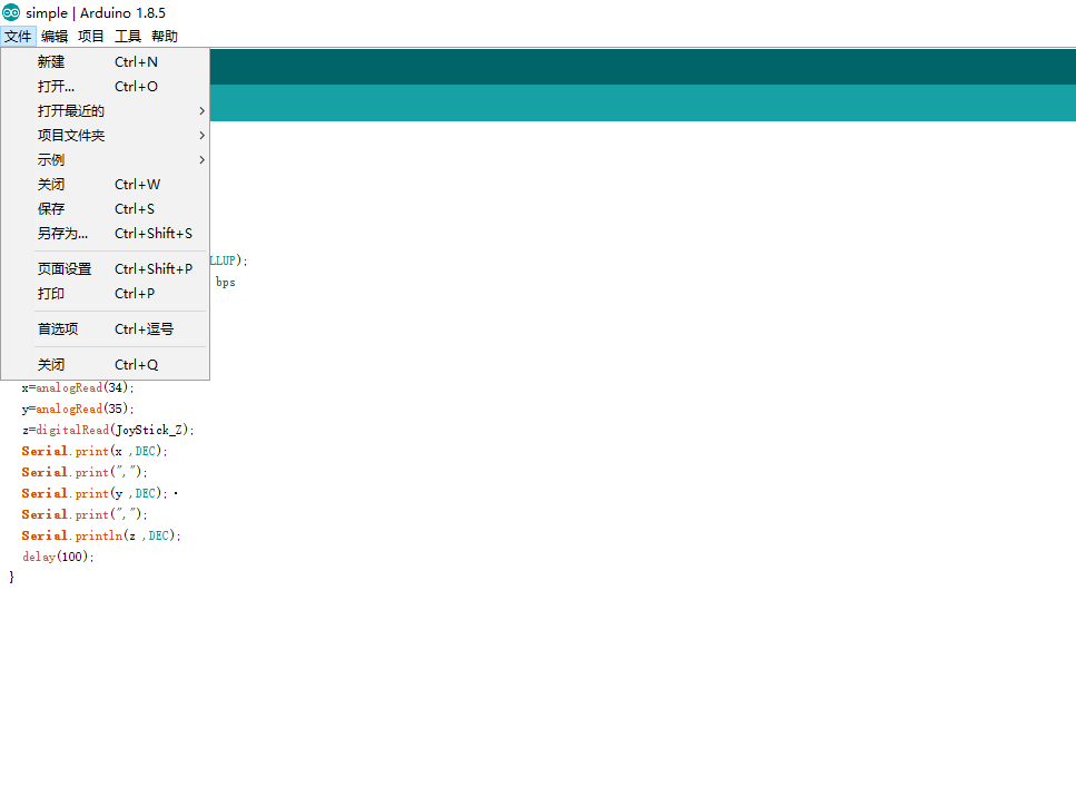
上面,我们对什么是单片机,以及单片机上面都有哪些引脚,都具备那些功能做了一个解释,那么接下来我们讲解一下 ESP32 开发环境在 Arduino 上面的一个配置。点击首选项
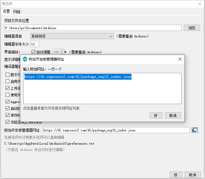
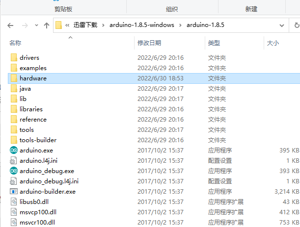
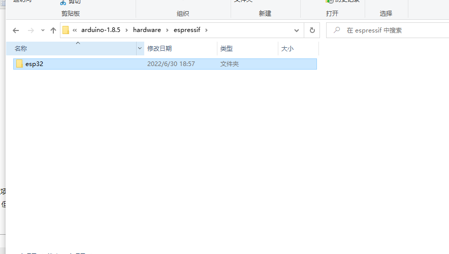
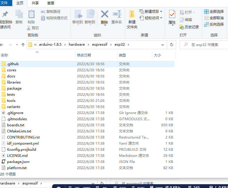
在此处可以配置项目文件夹,新建项目的存放文件夹,以及开发板的配置,点击附加的开发板网址,在弹出的界面中写入https://dl.espressif.com/dl/package_esp32_index.json,这个网址,用来配置ESP32的相关开发包。然后可以在工具,开发板,开发板管理中搜索ESP32,然后点击安装即可,但是此处需要梯子才可以下载,否则下载会很慢,可以自己去GITHUB下载后然后放在Arduino本地新建一个hardware文件夹,里面文件夹名称路径就和我图的一样否则环境配置失败是无法读取配置信息。
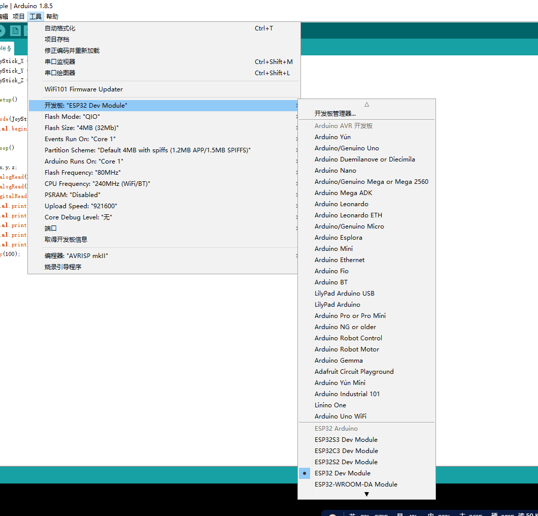
github 下载地址:https://github.com/espressif/arduino-esp32,下载后将里面的文件放进hardware/espressif/esp32文件夹中去,然后点击tools/get.exe,会去下载配置环境等待结束就可以找到ESP32的开发板,这中间下载速度可能会很慢,我会把所有的东西一并上传,然后下载稍作修改后就可以使用了。
下载地址:http://121.43.235.192:8082/s/Be88gki4eSFSMFs
结语
其实使用 VSCODE 也可以开发这个在 Arduino 上配置好之后,在 Vscode 中下载 Arduino 插件即可使用 Vscode 进行配置,取决于开发者,同时 VSC 开发还可以直接使用原生 c 语言进行开发,
可以参考 i 乐鑫官网给出的步骤,快速入门 - ESP32 - — ESP-IDF 编程指南 v4.4.2 文档 (espressif.com),这个文档还是很不错,使用原生 c 语言进行开发,其难度也相较 Arduino 难一些,我是刚开始使用这个环境开发的,后来换成了 Arduino 相对简单一些,同时还可以像 c#的 nuget 一样去搜索自己想要的库,同时也有例子,相对简单一些。
后续文章会玩一些简单的电子元器件,今年做智能小车一共做了三个,同时买的电子元器件也有很多,后续我会一一带大家去学习,去玩,然后有必要的话,也会直播做一些讲解,方便更好的入门学习,有兴趣的小伙伴可以持续关注,环境方面不懂的也可以随时加这个群找我,这个群,用来对单片机感兴趣的小伙伴的专属群,大家一起学习一起进步,目前玩的是 ESP 的板子,后面也会使用 51 或者 STM 系列的,有兴趣的可以一起研究,一起学习。